 | ||
| About typical replicated data cluster configuration | ||
|---|---|---|
| Prev | About setting up a replicated data cluster configuration | Next |
| ||
| About typical replicated data cluster configuration | ||
|---|---|---|
| Prev | About setting up a replicated data cluster configuration | Next |
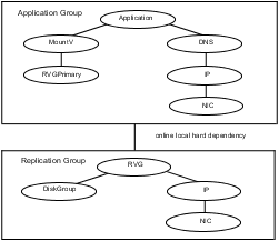
Figure: Dependency chart of a typical RDC configuration depicts a dependency chart of a typical RDC configuration.
In this example, a single-instance Oracle database is configured as a VCS service group (oragroup) on a four-node cluster, with two nodes in the primary RDC system zone and two in the secondary RDC system zone. In the event of a failure on the primary node, VCS fails over Oracle to the second node in the primary zone.