 | ||
| Sample configuration: links crossing IP routers | ||
|---|---|---|
| Prev | Manually configuring LLT over UDP using IPv6 | Next |
| ||
| Sample configuration: links crossing IP routers | ||
|---|---|---|
| Prev | Manually configuring LLT over UDP using IPv6 | Next |
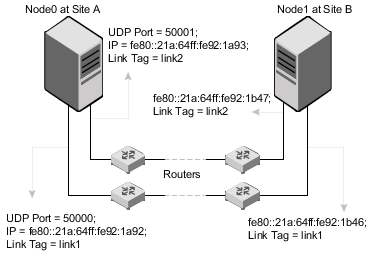
Figure: A typical configuration of links crossing an IP router depicts a typical configuration of links crossing an IP router employing LLT over UDP. The illustration shows two nodes of a four-node cluster.
The configuration that the following /etc/llttab file represents for Node 1 has links crossing IP routers. Notice that IPv6 addresses are shown for each link on each peer node. In this configuration multicasts are disabled.
set-node Node1
set-cluster 1

link link1 udp6 - udp6 50000 - fe80::21a:64ff:fe92:1a92 -
link link1 udp6 - udp6 50001 - fe80::21a:64ff:fe92:1a93 -

#set address of each link for all peer nodes in the cluster
#format: set-addr node-id link tag-name address
set-addr 0 link1 fe80::21a:64ff:fe92:1b46
set-addr 0 link2 fe80::21a:64ff:fe92:1b47
set-addr 2 link1 fe80::21a:64ff:fe92:1d70
set-addr 2 link2 fe80::21a:64ff:fe92:1d71
set-addr 3 link1 fe80::209:6bff:fe1b:1c94
set-addr 3 link2 fe80::209:6bff:fe1b:1c95

#disable LLT multicasts
set-bcasthb     0
set-arp         0
The /etc/llttab file on Node 0 resembles:
set-node Node0
set-cluster 1

link link1 udp6 - udp6 50000 - fe80::21a:64ff:fe92:1b46 -
link link2 udp6 - udp6 50001 - fe80::21a:64ff:fe92:1b47 -

#set address of each link for all peer nodes in the cluster
#format: set-addr node-id link tag-name address
set-addr 1 link1 fe80::21a:64ff:fe92:1a92
set-addr 1 link2 fe80::21a:64ff:fe92:1a93
set-addr 2 link1 fe80::21a:64ff:fe92:1d70
set-addr 2 link2 fe80::21a:64ff:fe92:1d71
set-addr 3 link1 fe80::209:6bff:fe1b:1c94
set-addr 3 link2 fe80::209:6bff:fe1b:1c95

#disable LLT multicasts
set-bcasthb     0
set-arp         0