 | ||
| Configuring IBM PowerVM LPAR guest for disaster recovery | ||
|---|---|---|
| Prev | Configuring for disaster recovery in virtualized environments | Next |
| ||
| Configuring IBM PowerVM LPAR guest for disaster recovery | ||
|---|---|---|
| Prev | Configuring for disaster recovery in virtualized environments | Next |
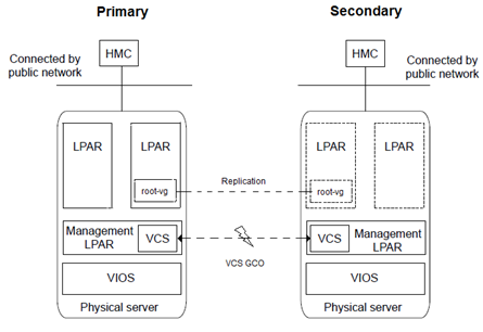
The IBM PowerVM is configured for disaster recovery by replicating the boot disk by using the replication methods like Hitachi TrueCopy, EMC SRDF, IBM duplicating, cloning rootvg technology, and so on. The network configuration for the LPAR on the primary site may not be effective on the secondary site, if the two sites are in the different IP subnets. To apply the different network configurations on the different sites, you will need to make additional configuration changes to the LPAR resource.
To configure LPAR for disaster recovery, you need to configure VCS on both the sites in the management LPARs with the GCO option. See the Cluster Server Administrator's Guide for more information about the global clusters.
Perform the following steps to set up the LPAR guest (managed LPAR) for disaster recovery:
VRTSvcsnr fileset from the VCS installation media. This fileset installs the vcs-reconfig service in the LPAR guest. This service ensures that the site-specific-network parameters are applied when the LPAR boots. You can install the VRTSvcsnr fileset by performing the following steps: # mkdir /<temp_dir> # cp <media>/pkgs/VRTSvcsnr.bff /<tmp_dir> # cd /<temp_dir> # installp -a -d VRTSvcsnr.bff VRTSvcsnr
Set the value of the ConfigureNetwork attribute to 1 from the DROpts attribute to make the changes effective. The LPAR agent does not apply to the DROpts attributes for the guest LPAR, if the value of the ConfigureNetwork attribute is 0. For more info about DROpts attribute see the Cluster Server Bundled Agents Reference Guide.
For more information about the appropriate VCS replication agent that is used to configure the replication resource, you can visit our website at the following URL: https://sort.veritas.com/agents
The replication resource ensures that when the resource is online in a site, the underlying replicated devices are in the primary mode, and the remote devices are in the secondary mode. Thus, when the LPAR resource is online, the underlying storage is always in the read-write mode.
Figure: Sample resource dependency diagram for NPIV base rootvg replication using the hardware replication technology
When the LPAR is online, the LPAR agent creates a private VLAN (with VLAN ID 123) between the management LPAR and the managed LPAR. The VLAN is used to pass the network parameters specified in the DROpts attribute to the managed LPAR. When the managed LPAR boots, it starts the vcs-reconfig service that requests for the network configuration from the management LPAR. As a result, the network configuration is resent, as a part of the response through the same VLAN. The vcs-reconfig service subsequently applies this configuration when the appropriate commands are run.