 | ||
| About preventing data corruption with I/O fencing | ||
|---|---|---|
| Prev | About I/O fencing | Next |
I/O fencing is a feature that prevents data corruption in the event of a communication breakdown in a cluster.
To provide high availability, the cluster must be capable of taking corrective action when a node fails. In this situation, SF Oracle RAC configures its components to reflect the altered membership.
Problems arise when the mechanism that detects the failure breaks down because symptoms appear identical to those of a failed node. For example, if a system in a two-node cluster fails, the system stops sending heartbeats over the private interconnects. The remaining node then takes corrective action. The failure of the private interconnects, instead of the actual nodes, presents identical symptoms and causes each node to determine its peer has departed. This situation typically results in data corruption because both nodes try to take control of data storage in an uncoordinated manner.
In addition to a broken set of private networks, other scenarios can generate this situation. If a system is so busy that it appears to stop responding or "hang," the other nodes could declare it as dead. This declaration may also occur for the nodes that use the hardware that supports a "break" and "resume" function. When a node drops to PROM level with a break and subsequently resumes operations, the other nodes may declare the system dead. They can declare it dead even if the system later returns and begins write operations.
SF Oracle RAC uses I/O fencing to remove the risk that is associated with split-brain. I/O fencing allows write access for members of the active cluster. It blocks access to storage from non-members.
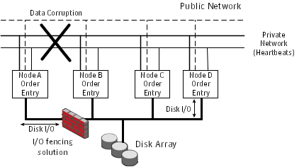
Figure: Private network disruption and I/O fencing solution displays a schematic of a four node cluster, each node writing order entries to the connected disk array. When the private network connection between the four nodes is disrupted (between Node A and the other 3 nodes in the figure below), a split-brain situation occurs with the possibility of data corruption to the disk array. The I/O fencing process prevents split-brain and any data corruption by fencing off Node A from the cluster.
SCSI-3 Persistent Reservations (SCSI-3 PR) are required for I/O fencing and resolve the issues of using SCSI reservations in a clustered SAN environment. SCSI-3 PR enables access for multiple nodes to a device and simultaneously blocks access for other nodes.
SCSI-3 reservations are persistent across SCSI bus resets and support multiple paths from a host to a disk. In contrast, only one host can use SCSI-2 reservations with one path. If the need arises to block access to a device because of data integrity concerns, only one host and one path remain active. The requirements for larger clusters, with multiple nodes reading and writing to storage in a controlled manner, make SCSI-2 reservations obsolete.
SCSI-3 PR uses a concept of registration and reservation. Each system registers its own "key" with a SCSI-3 device. Multiple systems registering keys form a membership and establish a reservation, typically set to "Write Exclusive Registrants Only." The WERO setting enables only registered systems to perform write operations. For a given disk, only one reservation can exist amidst numerous registrations.
With SCSI-3 PR technology, blocking write access is as easy as removing a registration from a device. Only registered members can "eject" the registration of another member. A member wishing to eject another member issues a "preempt and abort" command. Ejecting a node is final and atomic; an ejected node cannot eject another node. In SF Oracle RAC, a node registers the same key for all paths to the device. A single preempt and abort command ejects a node from all paths to the storage device.
I/O fencing, provided by the kernel-based fencing module (vxfen), performs identically on node failures and communications failures. When the fencing module on a node is informed of a change in cluster membership by the GAB module, it immediately begins the fencing operation. The node tries to eject the key for departed nodes from the coordinator disks using the preempt and abort command. When the node successfully ejects the departed nodes from the coordinator disks, it also ejects the departed nodes from the data disks. In a split-brain scenario, both sides of the split would race for control of the coordinator disks. The side winning the majority of the coordinator disks wins the race and fences the loser. The loser then panics and restarts the system.
The vxfen driver connects to GAB port b to intercept cluster membership changes (reconfiguration messages). During a membership change, the fencing driver determines which systems are members of the cluster to allow access to shared disks.
After completing fencing operations, the driver passes reconfiguration messages to higher modules. CVM handles fencing of data drives for shared disk groups. After a node successfully joins the GAB cluster and the driver determines that a preexisting split-brain does not exist, CVM can import all shared disk groups. The CVM master coordinates the order of import and the key for each disk group. As each slave joins the cluster, it accepts the CVM list of disk groups and keys, and adds its proper digit to the first byte of the key. Each slave then registers the keys with all drives in the disk groups.
The shared storage for SF Oracle RAC must support SCSI-3 persistent reservations to enable I/O fencing. SF Oracle RAC involves two types of shared storage:
Data disks - Store shared data
See About data disks.
Coordination points - Act as a global lock during membership changes
Data disks are standard disk devices for data storage and are either physical disks or RAID Logical Units (LUNs).
These disks must support SCSI-3 PR and must be part of standard VxVM or CVM disk groups. CVM is responsible for fencing data disks on a disk group basis. Disks that are added to a disk group and new paths that are discovered for a device are automatically fenced.
Coordination points provide a lock mechanism to determine which nodes get to fence off data drives from other nodes. A node must eject a peer from the coordination points before it can fence the peer from the data drives. SF Oracle RAC prevents split-brain when vxfen races for control of the coordination points and the winner partition fences the ejected nodes from accessing the data disks.
The coordination points can either be disks or servers or both.
Disks that act as coordination points are called coordinator disks. Coordinator disks are three standard disks or LUNs set aside for I/O fencing during cluster reconfiguration. Coordinator disks do not serve any other storage purpose in the SF Oracle RAC configuration.
You can configure coordinator disks to use Veritas Volume Manager Dynamic Multi-pathing (DMP) feature. Dynamic Multi-pathing (DMP) allows coordinator disks to take advantage of the path failover and the dynamic adding and removal capabilities of DMP. So, you can configure I/O fencing to use either DMP devices or the underlying raw character devices. I/O fencing uses SCSI-3 disk policy that is either raw or dmp based on the disk device that you use. The disk policy is dmp by default.
The coordination point server (CP server) is a software solution which runs on a remote system or cluster. CP server provides arbitration functionality by allowing the SF Oracle RAC cluster nodes to perform the following tasks:
Self-register to become a member of an active SF Oracle RAC cluster (registered with CP server) with access to the data drives
Check which other nodes are registered as members of this active SF Oracle RAC cluster
Forcefully unregister other nodes (preempt) as members of this active SF Oracle RAC cluster
In short, the CP server functions as another arbitration mechanism that integrates within the existing I/O fencing module.
Multiple SF Oracle RAC clusters running different operating systems can simultaneously access the CP server. TCP/IP based communication is used between the CP server and the SF Oracle RAC clusters.
Table: I/O fencing scenarios describes how I/O fencing works to prevent data corruption in different failure event scenarios. For each event, review the corrective operator actions.
Table: I/O fencing scenarios
|
Event |
Node A: What happens? |
Node B: What happens? |
Operator action |
|---|---|---|---|
|
Both private networks fail. |
Node A races for majority of coordination points. If Node A wins race for coordination points, Node A ejects Node B from the shared disks and continues. |
Node B races for majority of coordination points. If Node B loses the race for the coordination points, Node B panics and removes itself from the cluster. |
When Node B is ejected from cluster, repair the private networks before attempting to bring Node B back. |
|
Both private networks function again after event above. |
Node A continues to work. |
Node B has crashed. It cannot start the database since it is unable to write to the data disks. |
Restart Node B after private networks are restored. |
|
One private network fails. |
Node A prints message about an IOFENCE on the console but continues. |
Node B prints message about an IOFENCE on the console but continues. |
Repair private network. After network is repaired, both nodes automatically use it. |
|
Node A hangs. |
Node A is extremely busy for some reason or is in the kernel debugger. When Node A is no longer hung or in the kernel debugger, any queued writes to the data disks fail because Node A is ejected. When Node A receives message from GAB about being ejected, it panics and removes itself from the cluster. |
Node B loses heartbeats with Node A, and races for a majority of coordination points. Node B wins race for coordination points and ejects Node A from shared data disks. |
Repair or debug the node that hangs and reboot the node to rejoin the cluster. |
|
Nodes A and B and private networks lose power. Coordination points and data disks retain power. Power returns to nodes and they restart, but private networks still have no power. |
Node A restarts and I/O fencing driver (vxfen) detects Node B is registered with coordination points. The driver does not see Node B listed as member of cluster because private networks are down. This causes the I/O fencing device driver to prevent Node A from joining the cluster. Node A console displays: Potentially a preexisting split brain. Dropping out of the cluster. Refer to the user documentation for steps required to clear preexisting split brain. |
Node B restarts and I/O fencing driver (vxfen) detects Node A is registered with coordination points. The driver does not see Node A listed as member of cluster because private networks are down. This causes the I/O fencing device driver to prevent Node B from joining the cluster. Node B console displays: Potentially a preexisting split brain. Dropping out of the cluster. Refer to the user documentation for steps required to clear preexisting split brain. |
Resolve preexisting split-brain condition. |
|
Node A crashes while Node B is down. Node B comes up and Node A is still down. |
Node A is crashed. |
Node B restarts and detects Node A is registered with the coordination points. The driver does not see Node A listed as member of the cluster. The I/O fencing device driver prints message on console: Potentially a preexisting split brain. Dropping out of the cluster. Refer to the user documentation for steps required to clear preexisting split brain. |
Resolve preexisting split-brain condition. |
|
The disk array containing two of the three coordination points is powered off. No node leaves the cluster membership |
Node A continues to operate as long as no nodes leave the cluster. |
Node B continues to operate as long as no nodes leave the cluster. |
Power on the failed disk array so that subsequent network partition does not cause cluster shutdown, or replace coordination points. See Replacing I/O fencing coordinator disks when the cluster is online. |
|
The disk array containing two of the three coordination points is powered off. Node B gracefully leaves the cluster and the disk array is still powered off. Leaving gracefully implies a clean shutdown so that vxfen is properly unconfigured. |
Node A continues to operate in the cluster. |
Node B has left the cluster. |
Power on the failed disk array so that subsequent network partition does not cause cluster shutdown, or replace coordination points. See Replacing I/O fencing coordinator disks when the cluster is online. |
|
The disk array containing two of the three coordination points is powered off. Node B abruptly crashes or a network partition occurs between node A and node B, and the disk array is still powered off. |
Node A races for a majority of coordination points. Node A fails because only one of the three coordination points is available. Node A panics and removes itself from the cluster. |
Node B has left cluster due to crash or network partition. |
Power on the failed disk array and restart I/O fencing driver to enable Node A to register with all coordination points, or replace coordination points. |
This section discusses the CP server features.
The following CP server features are described:
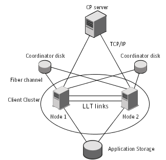
Figure: CP server, SF Oracle RAC cluster, and coordinator disks displays a configuration using a SF Oracle RAC cluster (with two nodes), a single CP server, and two coordinator disks. The nodes within the SF Oracle RAC cluster are connected to and communicate with each other using LLT links.
Three or more odd number of coordination points are required for I/O fencing. A coordination point can be either a CP server or a coordinator disk. A CP server provides the same functionality as a coordinator disk in an I/O fencing scenario. Therefore, it is possible to mix and match CP servers and coordinator disks for the purpose of providing arbitration.
Table: CP server deployment and migration scenarios describes the supported deployment and migration scenarios, and the procedures you must perform on the SF Oracle RAC cluster and the CP server.
Table: CP server deployment and migration scenarios
|
Scenario |
CP server |
SF Oracle RAC cluster |
Action required |
||
|---|---|---|---|---|---|
|
Setup of CP server for a SF Oracle RAC cluster for the first time |
New CP server |
New SF Oracle RAC cluster using CP server as coordination point |
On the designated CP server, perform the following tasks:
On the SF Oracle RAC cluster nodes, configure server-based I/O fencing. See the Veritas Storage Foundation for Oracle RAC Installation and Configuration Guide for the procedures. |
||
|
Add a new SF Oracle RAC cluster to an existing and operational CP server |
Existing and operational CP server |
New SF Oracle RAC cluster |
On the SF Oracle RAC cluster nodes, configure server-based I/O fencing. See the Veritas Storage Foundation for Oracle RAC Installation and Configuration Guide for the procedures. |
||
|
Replace the coordination point from an existing CP server to a new CP server |
New CP server |
Existing SF Oracle RAC cluster using CP server as coordination point |
On the designated CP server, perform the following tasks:
See the Veritas Storage Foundation for Oracle RAC Installation and Configuration Guide for the procedures. On a node in the SF Oracle RAC cluster, run the vxfenswap command to move to replace the CP server: See Replacing coordination points for server-based fencing in an online cluster. |
||
|
Replace the coordination point from an existing CP server to an operational CP server coordination point |
Operational CP server |
Existing SF Oracle RAC cluster using CP server as coordination point |
On the designated CP server, prepare to configure the new CP server manually. See the Veritas Storage Foundation for Oracle RAC Installation and Configuration Guide for the procedures. On a node in the SF Oracle RAC cluster, run the vxfenswap command to move to replace the CP server: See Replacing coordination points for server-based fencing in an online cluster. |
||
|
Enabling fencing in a SF Oracle RAC cluster with a new CP server coordination point |
New CP server |
Existing SF Oracle RAC cluster with fencing configured in disabled mode |
On the designated CP server, perform the following tasks:
See the Veritas Storage Foundation for Oracle RAC Installation and Configuration Guide for the procedures. On the SF Oracle RAC cluster nodes, perform the following:
|
||
|
Enabling fencing in a SF Oracle RAC cluster with an operational CP server coordination point |
Operational CP server |
Existing SF Oracle RAC cluster with fencing configured in disabled mode |
On the designated CP server, prepare to configure the new CP server. See the Veritas Storage Foundation for Oracle RAC Installation and Configuration Guide for this procedure. On the SF Oracle RAC cluster nodes, perform the following tasks:
|
||
|
Enabling fencing in a SF Oracle RAC cluster with a new CP server coordination point |
New CP server |
Existing SF Oracle RAC cluster with fencing configured in scsi3 mode |
On the designated CP server, perform the following tasks:
See the Veritas Storage Foundation for Oracle RAC Installation and Configuration Guide for the procedures. Based on whether the cluster is online or offline, perform the following procedures: For a cluster that is online, perform the following task on the SF Oracle RAC cluster:
For a cluster that is offline, perform the following tasks on the SF Oracle RAC cluster:
|
||
|
Enabling fencing in a SF Oracle RAC cluster with an operational CP server coordination point |
Operational CP server |
Existing SF Oracle RAC cluster with fencing configured in disabled mode |
On the designated CP server, prepare to configure the new CP server. See the Veritas Storage Foundation for Oracle RAC Installation and Configuration Guide for this procedure. Based on whether the cluster is online or offline, perform the following procedures: For a cluster that is online, perform the following task on the SF Oracle RAC cluster:
For a cluster that is offline, perform the following tasks on the SF Oracle RAC cluster:
|
||
|
Refreshing registrations of SF Oracle RAC cluster nodes on coordination points (CP servers/ coordinator disks) without incurring application downtime |
Operational CP server |
Existing SF Oracle RAC cluster using the CP server as coordination point |
On the SF Oracle RAC cluster run the vxfenswap command to refresh the keys on the CP server: See Refreshing registration keys on the coordination points for server-based fencing. |
You can migrate between fencing configurations without incurring application downtime in the SF Oracle RAC clusters.
See Migrating from disk-based to server-based fencing in an online cluster.
Similarly, you can migrate from server-based fencing to disk-based fencing when you want to perform maintenance tasks on the CP server systems.
See Migrating from server-based to disk-based fencing in an online cluster.
You can either use the installer or manually migrate from disk-based fencing to server-based fencing without incurring application downtime in the SF Oracle RAC clusters.
See About migrating between disk-based and server-based fencing configurations.
You can also use response files to migrate between fencing configurations.
See Migrating between fencing configurations using response files.
Warning: |
The cluster might panic if any node leaves the cluster membership before the coordination points migration operation completes. |
This section covers the following procedures:
|
Migrating using the script-based installer |
See “To migrate from disk-based fencing to server-based fencing using the installer”. |
|
Migrating manually |
See “To manually migrate from disk-based fencing to server-based fencing”. |
To migrate from disk-based fencing to server-based fencing using the installer
# vxfenadm -d
For example, if SF Oracle RAC cluster uses disk-based fencing:
I/O Fencing Cluster Information:
================================
Fencing Protocol Version: 201
Fencing Mode: SCSI3
Fencing SCSI3 Disk Policy: dmp
Cluster Members:
		* 0 (galaxy)
		1 (nebula)
RFSM State Information:
		node 0 in state 8 (running)
		node 1 in state 8 (running)
# /opt/VRTS/install/installsfrac -fencing
The installsfrac program starts with a copyright message and verifies the cluster information.
Note the location of log files which you can access in the event of any problem with the configuration process.
The installer verifies whether I/O fencing is configured in enabled mode.
Select the fencing mechanism to be configured in this
Application Cluster [1-4,q] 4
Select the coordination points you would like to remove
from the currently configured coordination points:
   1) emc_clariion0_62
   2) emc_clariion0_65
   3) emc_clariion0_66
   4) All
   5) None
   b) Back to previous menu
Enter the options separated by spaces: [1-5,b,q,?] (5)? 1 2
If you want to migrate to server-based fencing with no coordinator disks, type 4 to remove all the coordinator disks.
If you want to migrate to server-based fencing configuration with a mix of coordination points, the number you enter at this prompt must be a total of both the new CP servers and the new coordinator disks.
If you want to migrate to server-based fencing with no coordinator disks, type 0 at this prompt.
Review the output as the installer performs the following tasks:
Would you like to send the information about this installation
to Symantec to help improve installation in the future? [y,n,q,?] (y) y
# vxfenadm -d
For example, after the migration from disk-based fencing to server-based fencing in the SF Oracle RAC cluster:
I/O Fencing Cluster Information:
================================
Fencing Protocol Version: 201
Fencing Mode: Customized
Fencing Mechanism: cps
Cluster Members:
		* 0 (galaxy)
		1 (nebula)
RFSM State Information:
		node 0 in state 8 (running)
		node 1 in state 8 (running)
# vxfenconfig -l
To manually migrate from disk-based fencing to server-based fencing
# vxfenadm -d
For example, if SF Oracle RAC cluster uses disk-based fencing:
I/O Fencing Cluster Information:
================================
Fencing Protocol Version: 201
Fencing Mode: SCSI3
Fencing SCSI3 Disk Policy: dmp
Cluster Members:
		* 0 (galaxy)
		1 (nebula)
RFSM State Information:
		node 0 in state 8 (running)
		node 1 in state 8 (running)
/etc/vxfenmode.test file on each SF Oracle RAC cluster node with the fencing configuration changes such as the CP server information.Refer to the sample vxfenmode files in the /etc/vxfen.d folder.
# vxfenswap [-n]
Review the message that the utility displays and confirm whether you want to commit the change.
If you do not want to commit the new fencing configuration changes, press Enter or answer n at the prompt.
Do you wish to commit this change? [y/n] (default: n) n
If you want to commit the new fencing configuration changes, answer y at the prompt.
Do you wish to commit this change? [y/n] (default: n) y
If the utility successfully commits, the utility moves the /etc/vxfenmode.test file to the /etc/vxfenmode file.
# vxfenadm -d
For example, after the migration from disk-based fencing to server-based fencing in the SF Oracle RAC cluster:
I/O Fencing Cluster Information:
================================
Fencing Protocol Version: 201
Fencing Mode: Customized
Fencing Mechanism: cps
Cluster Members:
		* 0 (galaxy)
		1 (nebula)
RFSM State Information:
		node 0 in state 8 (running)
		node 1 in state 8 (running)
# vxfenconfig -l
You can either use the installer or manually migrate from server-based fencing to disk-based fencing without incurring application downtime in the SF Oracle RAC clusters.
See About migrating between disk-based and server-based fencing configurations.
You can also use response files to migrate between fencing configurations.
See Migrating between fencing configurations using response files.
Warning: |
The cluster might panic if any node leaves the cluster membership before the coordination points migration operation completes. |
This section covers the following procedures:
|
Migrating using the script-based installer |
See “To migrate from server-based fecing to disk-based fencing using the installer”. |
|
Migrating manually |
See “To manually migrate from server-based fencing to disk-based fencing”. |
To migrate from server-based fecing to disk-based fencing using the installer
# vxfenadm -d
For example, if the SF Oracle RAC cluster uses server-based fencing, the output appears similar to the following:
I/O Fencing Cluster Information:
================================
Fencing Protocol Version: 201
Fencing Mode: Customized
Fencing Mechanism: cps
Cluster Members:
		* 0 (galaxy)
		1 (nebula)
RFSM State Information:
		node 0 in state 8 (running)
		node 1 in state 8 (running)
# /opt/VRTS/install/installsfrac -fencing
The installsfrac program starts with a copyright message and verifies the cluster information.
Note the location of log files which you can access in the event of any problem with the configuration process.
The installer verifies whether I/O fencing is configured in enabled mode.
Select the fencing mechanism to be configured in this
Application Cluster [1-4,q] 4
Select the coordination points you would like to remove
from the currently configured coordination points:
   1) emc_clariion0_62
   2) [10.209.80.197]:14250,[10.209.80.199]:14300
   3) [10.209.80.198]:14250
   4) All
   5) None
   b) Back to previous menu
Enter the options separated by spaces: [1-5,b,q,?] (5)? 2 3
List of available disks:
   1) emc_clariion0_61
   2) emc_clariion0_65
   3) emc_clariion0_66
   b) Back to previous menu
Select 2 disk(s) as coordination points. Enter the disk options
separated by spaces: [1-3,b,q]2 3
Select the vxfen mode: [1-2,b,q,?] (1) 1
The installer initializes the coordinator disks and the coordinator disk group, and deports the disk group. Press Enter to continue.
vxfenmode.test file on all nodes and runs the vxfenswap script.Note the location of the vxfenswap.log file which you can access in the event of any problem with the configuration process.
The installer cleans up the application cluster information from the CP servers.
Would you like to send the information about this installation
to Symantec to help improve installation in the future? [y,n,q,?] (y) y
# vxfenadm -d
For example, after the migration from server-based fencing to disk-based fencing in the SF Oracle RAC cluster:
I/O Fencing Cluster Information:
================================
Fencing Protocol Version: 201
Fencing Mode: SCSI3
Fencing SCSI3 Disk Policy: dmp
Cluster Members:
		* 0 (galaxy)
		1 (nebula)
RFSM State Information:
		node 0 in state 8 (running)
		node 1 in state 8 (running)
# vxfenconfig -l
To manually migrate from server-based fencing to disk-based fencing
# vxfenadm -d
For example, if SF Oracle RAC cluster uses server-based fencing:
I/O Fencing Cluster Information:
================================
Fencing Protocol Version: 201
Fencing Mode: Customized
Fencing Mechanism: cps
Cluster Members:
		* 0 (galaxy)
		1 (nebula)
RFSM State Information:
		node 0 in state 8 (running)
		node 1 in state 8 (running)
/etc/vxfenmode.test file with the fencing configuration changes such as the scsi3 disk policy information.Refer to the sample vxfenmode files in the /etc/vxfen.d folder.
# vxfenswap -g diskgroup [-n]
Review the message that the utility displays and confirm whether you want to commit the change.
If you do not want to commit the new fencing configuration changes, press Enter or answer n at the prompt.
Do you wish to commit this change? [y/n] (default: n) n
If you want to commit the new fencing configuration changes, answer y at the prompt.
Do you wish to commit this change? [y/n] (default: n) y
If the utility successfully commits, the utility moves the /etc/vxfenmode.test file to the /etc/vxfenmode file.
# vxfenadm -d
For example, after the migration from server-based fencing to disk-based fencing in the SF Oracle RAC cluster:
I/O Fencing Cluster Information:
================================
Fencing Protocol Version: 201
Fencing Mode: SCSI3
Fencing SCSI3 Disk Policy: dmp
Cluster Members:
		* 0 (galaxy)
		1 (nebula)
RFSM State Information:
		node 0 in state 8 (running)
		node 1 in state 8 (running)
# vxfenconfig -l
Typically, you can use the response file that the installer generates after you migrate between I/O fencing configurations. Edit these response files to perform an automated fencing reconfiguration in the SF Oracle RAC cluster.
To configure I/O fencing using response files
# vxfenadm -d
For example, if SF Oracle RAC cluster uses disk-based fencing:
I/O Fencing Cluster Information:
================================
Fencing Protocol Version: 201
Fencing Mode: SCSI3
Fencing SCSI3 Disk Policy: dmp
Cluster Members:
		* 0 (galaxy)
		1 (nebula)
RFSM State Information:
		node 0 in state 8 (running)
		node 1 in state 8 (running)
For example, if the SF Oracle RAC cluster uses server-based fencing:
I/O Fencing Cluster Information:
================================
Fencing Protocol Version: 201
Fencing Mode: Customized
Fencing Mechanism: cps
Cluster Members:
		* 0 (galaxy)
		1 (nebula)
RFSM State Information:
		node 0 in state 8 (running)
		node 1 in state 8 (running)
Review the sample files to reconfigure I/O fencing.
See Sample response file to migrate from disk-based to server-based fencing.
See Sample response file to migrate from server-based fencing to disk-based fencing.
See Sample response file to migrate from single CP server-based fencing to server-based fencing.
See Response file variables to migrate between fencing configurations.
# /opt/VRTS/install/installsfrac -responsefile /tmp/response_file
Where /tmp/response_file is the response file's full path name.
The following is a sample response file to migrate from disk-based fencing with three coordinator disks to server-based fencing with one CP server and two coordinator disks:
$CFG{disks_to_remove}=[ qw(emc_clariion0_62) ];
$CFG{fencing_cps}=[ qw(10.198.89.251)];
$CFG{fencing_cps_ports}{"10.198.89.204"}=14250;
$CFG{fencing_cps_ports}{"10.198.89.251"}=14250;
$CFG{fencing_cps_vips}{"10.198.89.251"}=[ qw(10.198.89.251 10.198.89.204) ];
$CFG{fencing_ncp}=1;
$CFG{fencing_option}=4;
$CFG{opt}{configure}=1;
$CFG{opt}{fencing}=1;
$CFG{prod}="SFRAC60";
$CFG{systems}=[ qw(galaxy nebula) ];
$CFG{vcs_clusterid}=22462;
$CFG{vcs_clustername}="rac_cluster101";
The following is a sample response file to migrate from server-based fencing with one CP server and two coordinator disks to disk-based fencing with three coordinator disks:
$CFG{fencing_disks}=[ qw(emc_clariion0_66) ];
$CFG{fencing_mode}="scsi3";
$CFG{fencing_ncp}=1;
$CFG{fencing_ndisks}=1;
$CFG{fencing_option}=4;
$CFG{opt}{configure}=1;
$CFG{opt}{fencing}=1;
$CFG{prod}="SFRAC60";
$CFG{servers_to_remove}=[ qw([10.198.89.251]:14250) ];
$CFG{systems}=[ qw(galaxy nebula) ];
$CFG{vcs_clusterid}=42076;
$CFG{vcs_clustername}="rac_cluster101";
The following is a sample response file to migrate from single CP server-based fencing to server-based fencing with one CP server and two coordinator disks:
$CFG{fencing_disks}=[ qw(emc_clariion0_62 emc_clariion0_65) ];
$CFG{fencing_dgname}="fendg";
$CFG{fencing_scsi3_disk_policy}="dmp";
$CFG{fencing_ncp}=2;
$CFG{fencing_ndisks}=2;
$CFG{fencing_option}=4;
$CFG{opt}{configure}=1;
$CFG{opt}{fencing}=1;
$CFG{prod}="SFRAC60";
$CFG{systems}=[ qw(galaxy nebula) ];
$CFG{vcs_clusterid}=42076;
$CFG{vcs_clustername}="rac_cluster101";
Table: Response file variables specific to migrate between fencing configurations lists the response file variables that specify the required information to migrate between fencing configurations for SF Oracle RAC.
Table: Response file variables specific to migrate between fencing configurations
If you want to configure a multi-node CP server cluster, install and configure SFHA on the CP server nodes. Otherwise, install and configure VCS on the single node.
In both the configurations, VCS provides local start and stop of the CP server process, taking care of dependencies such as NIC, IP address, and so on. Moreover, VCS also serves to restart the CP server process in case the process faults.
VCS can use multiple network paths to access a CP server. If a network path fails, CP server does not require a restart and continues to listen on one of the other available virtual IP addresses.
To make the CP server process highly available, you must perform the following tasks:
Note: |
Symantec recommends that you do not run any other applications on the single node or SFHA cluster that is used to host CP server. |
A single CP server can serve multiple SF Oracle RAC clusters. A common set of CP servers can serve up to 128 SF Oracle RAC clusters.
In a data center, TCP/IP communication between the SF Oracle RAC cluster (application cluster) and CP server must be made secure. The security of the communication channel involves encryption, authentication, and authorization.
The CP server node or cluster needs to confirm the authenticity of the SF Oracle RAC cluster nodes that communicate with it as a coordination point and only accept requests from known SF Oracle RAC cluster nodes. Requests from unknown clients are rejected as non-authenticated. Similarly, the fencing framework in SF Oracle RAC cluster must confirm that authentic users are conducting fencing operations with the CP server.
Entities on behalf of which authentication is done, are referred to as principals. On the SF Oracle RAC cluster nodes, the current VCS installer creates the Authentication Server credentials on each node in the cluster. It also creates vcsauthserver which authenticates the credentials. The installer then proceeds to start VCS in secure mode.
Typically, in an existing VCS cluster with security configured, vcsauthserver runs on each cluster node.
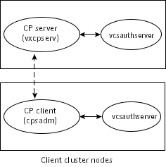
CP server and SF Oracle RAC cluster (application cluster) node communication involve the following entities:
Figure: End-To-end communication flow with security enabled on CP server and SF Oracle RAC clusters displays a schematic of the end-to-end communication flow with security enabled on CP server and SF Oracle RAC clusters (application clusters).
Communication flow between CP server and SF Oracle RAC cluster nodes with security configured on them is as follows:
Identities of CP server and SF Oracle RAC cluster nodes are configured on respective nodes by the VCS installer.
The cpsadm command gets the user name, domain type from the environment variables CPS_USERNAME, CPS_DOMAINTYPE. The user is expected to export these variables before running the cpsadm command manually. The customized fencing framework exports these environment variables internally before running the cpsadm commands.
The CP server process (vxcpserv) uses its own user (CPSERVER) which is added to the local vcsauthserver.
Getting credentials from authentication broker:
The cpsadm command tries to get the existing credentials that is present on the local node. The installer generates these credentials during fencing configuration.
The vxcpserv process tries to get the existing credentials that is present on the local node. The installer generates these credentials when it enables security.
Communication between CP server and SF Oracle RAC cluster nodes:
After the CP server establishes its credential and is up, it becomes ready to receive data from the clients. After the cpsadm command obtains its credentials and authenticates CP server credentials, cpsadm connects to the CP server. Data is passed over to the CP server.
On receiving data from a particular SF Oracle RAC cluster node, vxcpserv validates its credentials. If validation fails, then the connection request data is rejected.
This section discusses the security configuration details for the CP server and SF Oracle RAC cluster (application cluster).
The following are the settings for secure communication between the CP server and SF Oracle RAC cluster:
Installer creates a user with the following values:
Run the following commands on the CP server to verify the settings:
# export EAT_DATA_DIR=/var/VRTSvcs/vcsauth/data/CPSERVER
# /opt/VRTScps/bin/cpsat showcred
SF Oracle RAC cluster node(s) settings:
On SF Oracle RAC cluster, the installer creates a user for cpsadm during fencing configuration with the following values:
Run the following commands on the SF Oracle RAC cluster node(s) to verify the security settings:
# export EAT_DATA_DIR=/var/VRTSvcs/vcsauth/data/CPSADM
# /opt/VRTScps/bin/cpsat showcred
The users described above are used only for authentication for the communication between the CP server and the SF Oracle RAC cluster nodes.
For CP server's authorization, customized fencing framework on the SF Oracle RAC cluster uses the following user if security is configured:
CPSADM@VCS_SERVICES@cluster_uuid
where cluster_uuid is the application cluster's universal unique identifier.
For each SF Oracle RAC cluster node, this user must be registered on the CP server database before fencing starts on the SF Oracle RAC cluster node(s). This can be verified by issuing the following command:
# cpsadm -s cp_server -a list_users
The following is an example of the command output:
Username/Domain Type
CPSADM@VCS_SERVICES@77a2549c-1dd2-11b2-88d6-00306e4b2e0b/vx

Cluster Name / UUID                           Role
cluster1/{77a2549c-1dd2-11b2-88d6-00306e4b2e0b} Operator
In non-secure mode, only authorization is provided on the CP server. Passwords are not requested. Authentication and encryption are not provided. User credentials of "cpsclient@hostname" of "vx" domaintype are used by the customized fencing framework for communication between CP server or SF Oracle RAC cluster node(s).
For each SF Oracle RAC cluster node, this user must be added on the CP server database before fencing starts on the SF Oracle RAC cluster node(s). The user can be verified by issuing the following command:
# cpsadm -s cpserver -a list_users
The following is an example of the command output:
Username/Domain Type  Cluster Name / UUID                 Role
cpsclient@galaxy/vx   cluster1 / {f0735332-e3709c1c73b9}  Operator